|
The entire rear axle setup is being purchased from The Edge Products. It should be here mid August. I already have some
parts of it so heres some photo's. I will add photo's of how it goes together when i get to that stage.
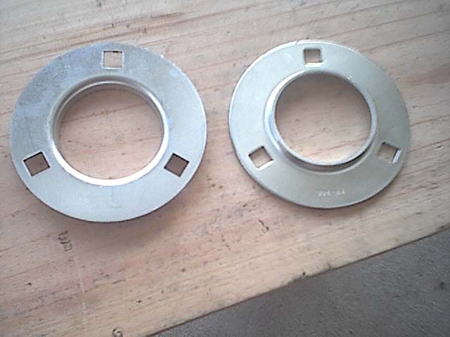
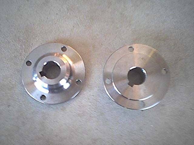
These are the rear axle bearing flanges which i brought from The Edge.
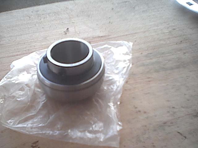
This is the 1 1/4 inch rear axle bearing from The Edge that fits into the bearing flanges (2 bearings required). My bearings
came with a small nipple on them which stopped it from fitting in the flanges, i just ground the nipple off as its not required.
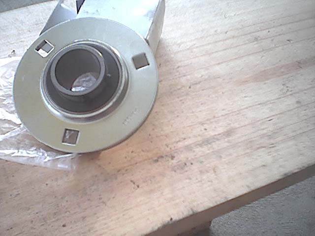
Picture below shows the bearing fitted in the flanges.
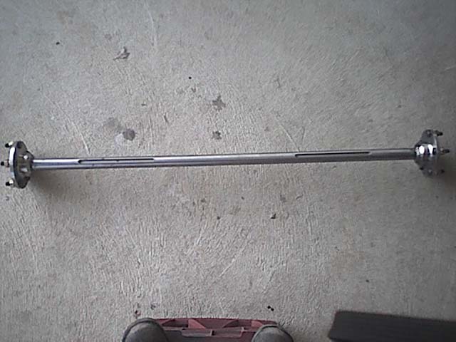
Below is the rear axle from The Edge. It comes with the HT holden hubs fitted and the keyways cut.
Pictured below is the sprocket and brake disk hubs. They are from the Edge. They are very good quality, they are very
chunky and machined very nicely.
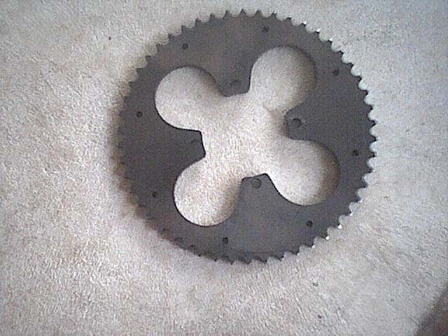
Below is the 50 tooth drive sprocket from the Edge. It fits onto the hubs pictured above and has holes drilled on the
outer circumfrence to fit chain guides to stop the chain coming off.
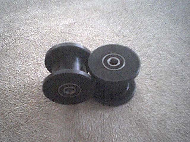
Below are the acetal chain tensioner rollers from the Edge. They are fitted with 8mm bearings.
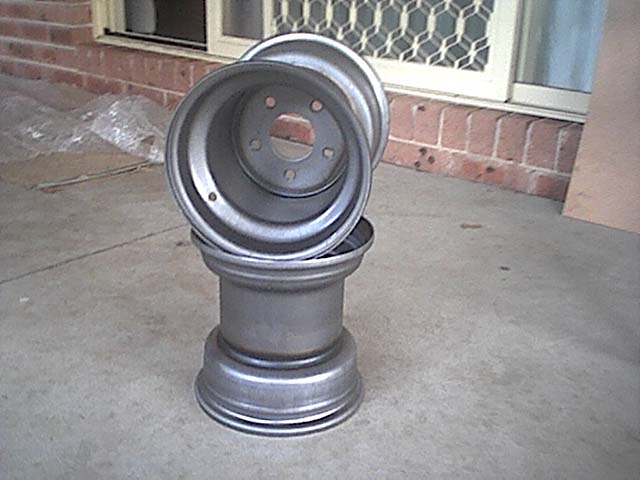
Below are the 9x9" rear wheels from the Edge. They are not yet painted but they will be painted gold like the front set
of wheels. They are the HT holden stud pattern. They look like they are wider than what they are tall.
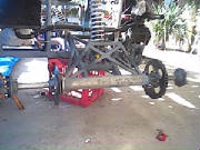
The axle is now installed on the buggy. It took me about a half day to fully install the axle to the rear swingarm. The
first step was to determine which way the axle was to be installed in the axle tube. The recommended way is to feed the axle
through the tube from the right hand side of the buggy. This way when you attach the wheel hub to the left hand side of the
axle with the allen head bolts, the spinning motion of the axle will help keep the bolts tight. These bolts also need loctite.
However before inserting the axle through the axle tube on the swingarm you need to make sure you first install
your spocket hub carrier and drive sprocket followed by the bearing flange and then the bearing (with grub screws facing out) which
will be installed on the right hand side of the axle (once the axle is installed through the axle tube you cannot get these
on).
Also be sure to use plenty of grease during the axle fitting process to aid putting the peices togther and also
to prevent corrosion forming on the axle shaft.
Now grease up the axle and insert it through the swingarm axle tube from the right side to the left.
Once its through you can now install your bearing (with grub screws facing out) to the left side of the axle, followed
by your bearing flange (and then caliper mount as i did) and brake disk and carrier, then the left wheel hub
can be installed and bolted on using loctite.
Now you can tighten up the bearing flanges around the bearings and then hit the axle with a rubber mallot (it will be
tight) until you are sure that the axle is located centrally on the swingarm (your 2 keyway cutouts should be equal length
on both sides). Now tighten the grub screws on the bearings (use loctite on all screws and bolts)
Now cut your keysteel to have a nice tight fit between the end of the keyway and the axle bearing. (The keysteel stops
the axle moving sideways and also transmits the drive to the brake disk/sprocket hubs). On end of the keysteel will have to
be rounded to match the axle cutout.
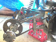
Once that is done the swingarm can be fitted to the buggy and then use a straight edge to line up the motor output sprocket
with the axle drive sprocket, then you can tighten the grub screws on the sprocket carrier to stop sideways movement on the
axle.
The brake disk is done the same way, just line it up so it is between the pads on the brake caliper and then tighten
the grub screws onto the axle.
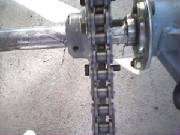
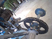
Picture is below of the keysteel installed on the drive sprocket side, on the right of the hub where the arrows are you
can see where the keysteel butts up to the bearing and the arrows on the left show the end of the keysteel where it comes
out of the end of the sprocket carrier.
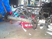
The chain tensioner was built as per the plans, the rollers for it i got from the Edge. I mounted it to the chassis in
the same position as the plans specify, but in order to mount it in this position i had to make up a custom mount bracket
from a peice of angle as i had notched the frame already to fit the engine in so i didnt have the crossmember on the mian
frame to mount the tensioner to. It was simple to modify and works the same as the original way would. Now the pivot bolt
for the tensioner goes through the peice of angle and then through the left rear engine mount. You can see better in the pics
what i mean.
|