|
For the steering i used a Mk2 Ford Escort steering rack which i modified as per the plans.
Please not that this is my method and your rack may be a different style from a different model.
I also did not unscrew and remove the ball joint housings from the rack as i was unable to, so i just cut the rack
as req'd and then re-welded it without removing the ball joint housings. If something doesn't seem right don't do it, do not
follow this method like the bible, use common sense. It is to be used only as a guide. However it worked great for my
rack assembly.
- 1st step was to clean it up when i got it home from the wreckers as it was filthy dirty. I removed the rubber
boots and then a quick clean with heavy duty degreaser had it spotless in no time..
- 2nd step was to remove the tie rod ends.
- 3rd step in modifying the rack was to cut away the long tube on the r/h side which houses the majority
of the rack inside it. Dimensions to cut the housing are in the plans. Be careful when cutting the outer housing that
you dont cut through the rack inside. What worked for me was to turn the housing and make small shallow cuts with a hacksaw until
it was free from the rest of the assembly.
- 4th step was to slide the cut housing as far to the right as possible to expose the rack beneath it.
Now what i did was cut the rack right through on the very last gear tooth (rack will still be longer than req'd) so that i
could then turn the steering all the way to the right and remove the rack completely from the housing. (The reason i did this
is because i could not remove the worm gear from the housing, and i wanted the rack removed to be able to mark the rack accurately
for cutting to size)
- 5th step was to remove the rack from the housing as described above. Now you have to cut the ball joint off
of the length of discarded rack, from memory i think i left approx 1 inch of rack connected to the right ball housing. Now
cut your peice of rack with the teeth on it to the req'd legth so it will end up being the length specified in the plans once
it is re-welded to the r/h ball joint (dont forget to allow for the length of the peice of rack on your r/h ball joint
housing when making your measurements).
- 6th step is once you have cut the rack to the required lengths is to grind a "V" into the
ends that butt up against one another for the weld to sit in. Now put your rack back into the housing
BEFORE RE-WELDING. Now you have to fit the escort rack bush (available from Edge or can be made from plans) to
the r/h side of the housing before you weld the parts together.
- 7th step is once the bush is fitted you can butt the two peices of rack together. My method for keeping the
rack perfectly straight when welding was to clamp the two peices of rack into the corner of a piece of steel angle and then
put 2 tack welds 180 degrees from one another to hold the rack straight. Now remove the piece of angle and then fully weld
the join then grind it flush
- 8th step for me was to apply grease or gear oil to the pack and pinion so it moves freely and smoothly
Next project with the rack will be lengthening the steering arms.
Sorry if i confused you with that method but i tried to give as much detail as possible. I wish i took pictures
of the process, it would have made explaining it much easier. And by the way I take no responsibility for wrongly made racks...
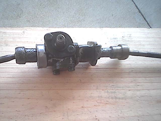
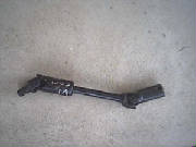
Pictures of my completed rack below.
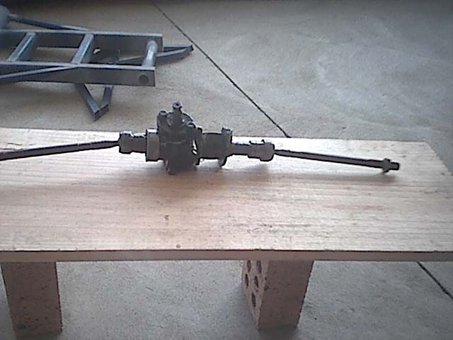
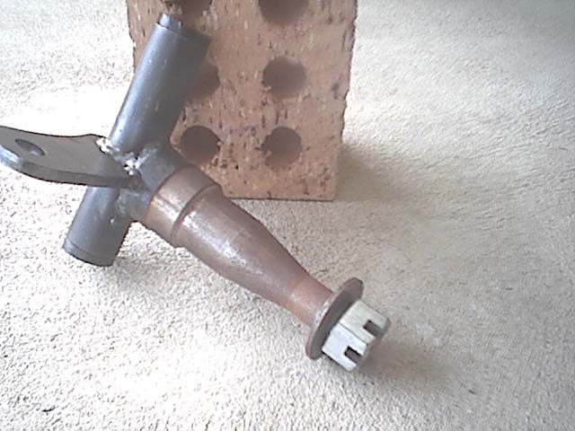
Below is the stub axle assembly i got from The Edge, it comes with pivot upright, steering arm and stub axle
fully welded. The corrosion on the bearing surface is because it has been laying around for a while...
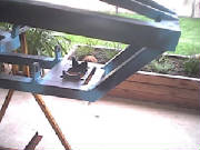
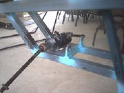
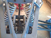
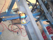
Below is a picture of the mount made by the Edge. It has been welded into the frame according to the plans.
The 2nd picture is of the escort rack in the mount. It fits nicely.
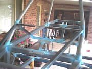
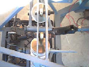
The pictures below are of the steering column mounts. The forward mount remains as per the plans, but the
rearward mount i have designed myself so that i can incorporate my dash into the design. The column will still sit at the
same dimensions and angle as per the plans.
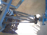
Below is the lower section of the VL commodore steering column. The right side connects to the escort
rack spline while the left side fits into the steering column and is then welded in place. This item was $30 from a local
wreckers.
Lengthening the rack tie rods
Lengthening the tie rods was quite an easy job. I found that it should be done after the front suspension
is set up (shocks fitted) so that your front swingarms are sitting at the correct angle so you can set up the tie rod
length appropriately.
The first thing i did was i cut the tie rods about 50mm up the shaft from the thread on the threaded
end, this part was to be re-welded on later once i had put the extension peice in to lengthen the tie rods. Once the tie rods
were cut, i then placed the rack in the mount on the buggy and made sure the rack was at dead centre which in my case was
1 and a half turns lock to lock, so dead centre for the rack is 3/4 of a turn in either direction.
Now line up your wheel hubs/stub axles so they are pointing dead straight ahead as though the buggy
is steering straight (doesn't matter if you are off dead straight a little as the tie rod thread adjustment will account for
this later on). Now once you have done this fit your tie rod swivel ends into your stub axle steering hole and screw
the cut off tie rod peice into the tie rod swivel ends until you have half the thread showing on the rod. You will end up
with something like the picture below.
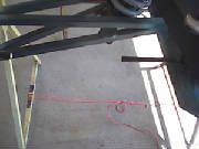
Now its time to fill the gap between the two peices of tie rod to connect them again. For this job
i am doing it my own way and not to the plans, i will end up with the same result though. I used a peice of 25x25mm angle
to act as a straight edge to align the cut off tie rods in the same plane, i then clamped them to the angle as shown below
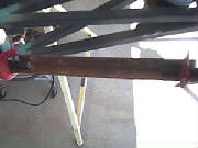
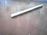
Now its just a matter of measuring the distance between the two cut peices of tie rod and cutting
a filler peice to fill the gap in between. I used 1/2 inch diameter BMS bar as my filler peice with the ends ground to
a "V" (chamfer) to be filled with weld when i reconnect the rods. That way i can grind the welds back smooth and
you wont even be able to see that the rods have been lengthened. Below is the filler peice for the r/h tie rod.
Now all thats left to do is to do the other side in the same way. Grind all your welds flush, give
a spray of primer and its finished. My rack with lengthened tie rods is pictured below.
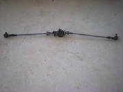
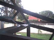
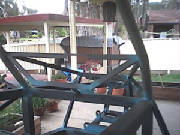
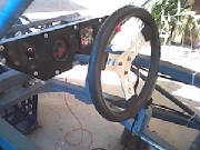
The steering system is now fully installed on the buggy. Its all connected and just needs adjusting
through the tie rod ends to get both wheels pointing dead straight once the wheels are fitted. Im very happy with how it turned
out. Also instead of welding the steering column pipe to the uni joint assembly where they connect as the plans specify i
put 2 bolts through it to make it removable as can be seen in the pics. It will still be as strong but will also be able to
be separated so i can pull the column out through the hole in the dash without having to disassemble it all to get it out.
Pics of the setup below.
|