|
I used 8mm plate for the rear as well as the front suspension arm mounts due to ease because i already had
a long piece of 8mm flatbar laying around. I cut it using a hacksaw which was not as much hard work as i thought it would
be. I used an 18 teeth per inch cutting blade.
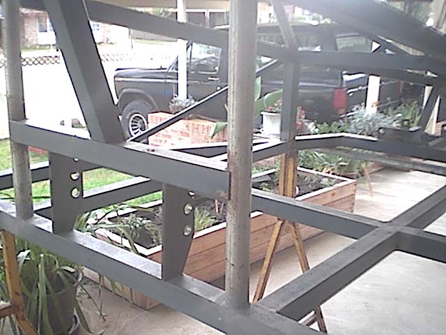
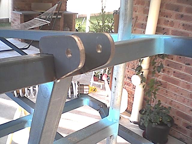
The front upper shock mounts are made from 6mm plate which i cut to the sizes shown in the plans with
a 18tpi hacksaw. I have drilled 3 holes on each side, the middle hole being the original mounting hole as specified in the
plans and the hole either side being for shock adjustment if necessary. I thought its easier to drill the extra holes now
than to find they may need to be drilled later on. To get the 30mm gap between the two mounts i cut two peices of pipe (white
in picture) and put them between the plates to give the perfect spacing as shown in the picture below.

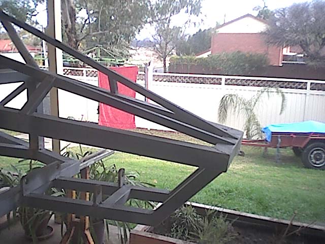
Below is a picture of the rear upper shock mount. Made from 8mm
steel. I set them at my own distance apart to suit the Edge's shocks. As you can see in the picture they are not exactly to
the plans. I did not cut the complete cutout to fit under the RHS as well because i did not have a tool to cut the peice out,
so i just cut it with 2 edges being welded to the RHS, it should still retain its strength. They look all wobbly and out of
line in the picture because of the cheap camera im using, but they are in fact nicely lined up.
|