|
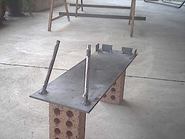
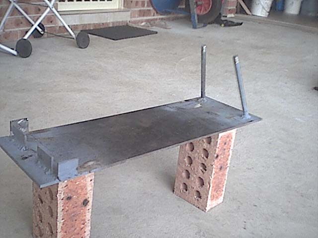
The jig was made as per the plans using a piece of flat plate as a sturdy and flat base for the swing arm to be constructed
on. I then measured out all the points on the peice of plate where the 12mm rod and pivot tube housing pieces were to be welded
on. I then cut two peices of 12mm rod to length and welded them in position, and then using castor and camber
angle jigs which i cut from sturdy cradboard, i used a rubber mallot to tap the rods and lean them over till they were at
the correct camber and castor as specified in the plans. I then welded the pivot tube housing plates in the correct position
at the other end of the jig,
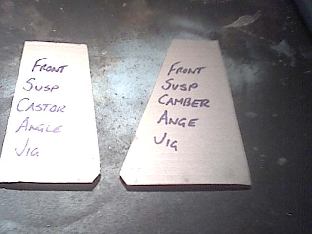
Below are the camber and castor jigs i made in order to get the correct angle on the 12mm rod in the jig. They are
just sturdy cardboard which have the camber and castor angles cut into them so you can check the 12mm rod angle on the jig
is correct. The small cutout in the bottom corners of the jigs is so they clear the weld around the base of the rods. These
are just an idea i thought up which might help you get your angles correct! My angles came out sweet.
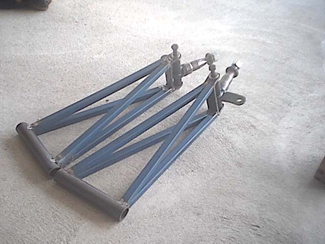
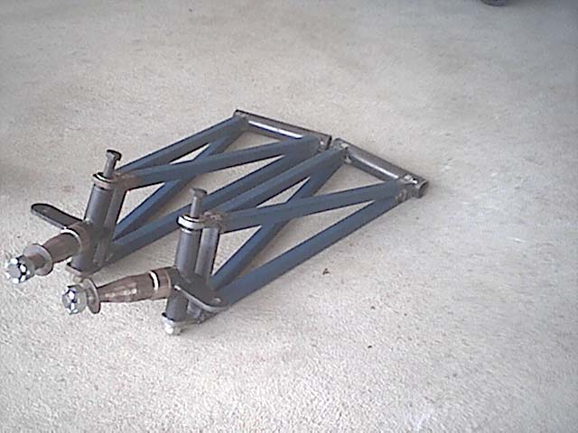
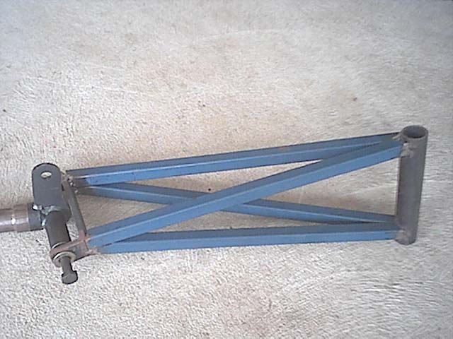
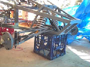
The swingarms are constructed from 25nb pipe, 20x20 rhs and 8mm flatbar for the stub axle cradle. The method for building
the left and right front swing arms is quite simple. Build the jig as per the plans, cut your pivot tube and construct the
stub axle cradle in accordance with the plans, then place the pivot tube and cradle in your jig and join the two parts
using 20x20 rhs. I am yet to add a shock mount until i work out what shock i will use.
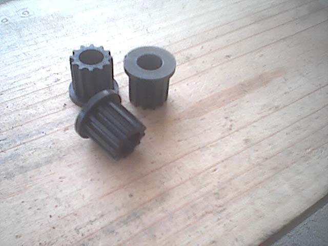
These are the injection molded acetal pivot bushes that i got from The Edge, they fit into the 25nb pivot tube on
the swingarms.
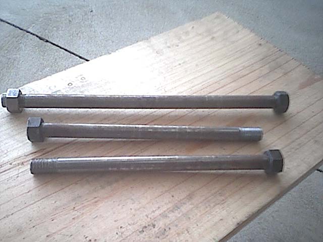
The bottom 2 bolts in the picture below are for the front suspension arms to pivot on. They are made from 16mm BMS
rod, and were threaded using a 5/8 UNF thread die. One end is only threaded 10mm or so so you can screw on a nut and then
weld it into place so it becomes the bolt head, the other end is threaded to the dimensions in the plans. The top bolt is
for the rear suspension.
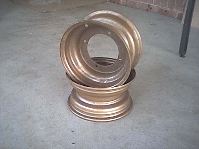
Below is a picture of the 10x5" front wheels. They are from The Edge but they have the 4 stud 156mm pcd stud pattern
because the other 5 stud HT holden stud pattern wheels are not in stock for a few more months. I am getting
custom trailer hubs made up to suit the wheels.
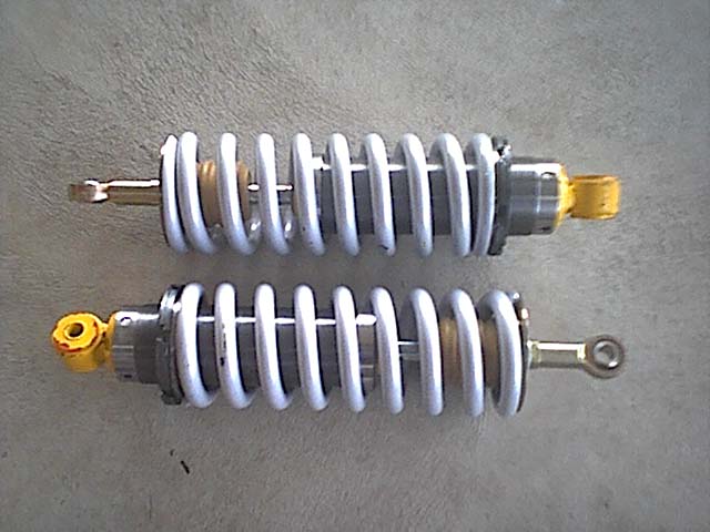
Below are the front shocks from The Edge. They have an eyelet on one end and and a conventional shock mount on the other
end. They are threaded all the way up the shaft which will allow for plenty of spring preload adjustment later on which is
good.
Shock mounts and shocks installation
I found out that the original front upper shock mounts which i had fabricated for the buggy were in the wrong position
as the top shock mount holes were too low and needed to be raised by approx 20mm to get correct swingarm angle with a
fully extended shock (approx 3 degrees neg camber at the stub axle). I asked Tony from the Edge and he said that if Edge shocks
(shock390) are being used then the distance between the centre of your upper shock mount hole and the top of the 30x30 RHS
of the lower frame needs to be 315mm. So i set out making new mounts which are now to the exact dimensions which
Tony specified. picture below.
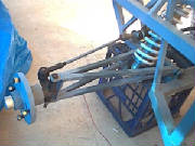
The lower shock mount pictured below are done to my own design, however the measurements are as to the plans, i just
didnt use the mount design specified in the plans. I would have liked to use the 1 inch drilled bms lower mounts as specified
but i didnt have any at the time and i had no way of making them up, so i just made up my own design because i was up
to that stage and didnt want to be delayed waiting for the parts. It should be as strong (only one way to find out). I used
50mm angle, 6mm thick for the forward lower shock mount on the front swingarm and i used 6mm flatbar as the rearward
mount on the front swingarm as can be seen in the picture below.
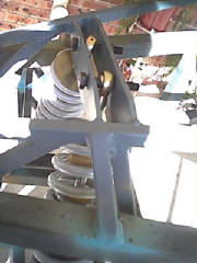
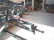
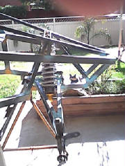
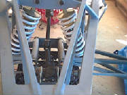
Below are pictures of the completed front swingarms with shocks fitted. The wheels sit at approx 0 degrees camber at
the moment, but once a bit of weight gets in they should be about 2-3 degrees negative camber, i'll just have to adjust
the stiffness of the shocks by adjusting the pre-load on the coil spring.
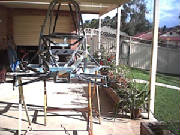
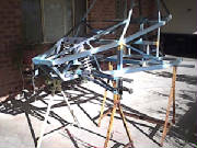
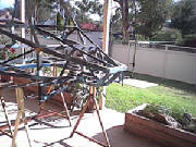
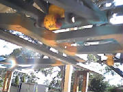
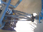
The front swingarms are now fully installed to the buggy and shouldn't need to be removed until after testing and painting
is done. All i need to do now is install the wheels once the tires are fitted to them and put longer bolts in for the lower
shock mounts. Pics of the setup below.
|