|
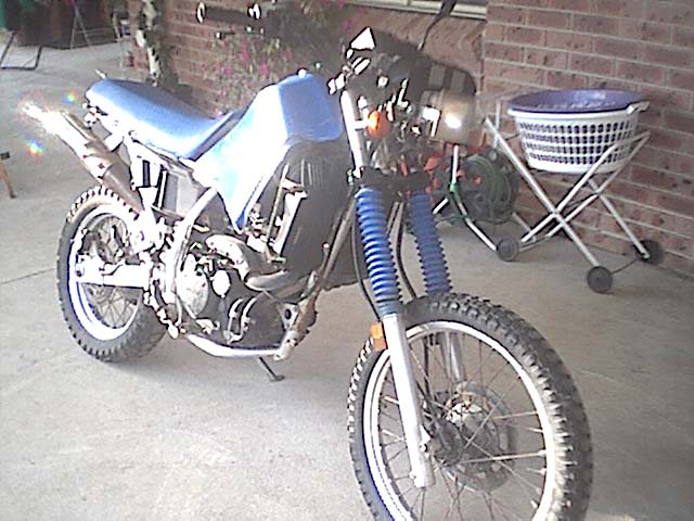
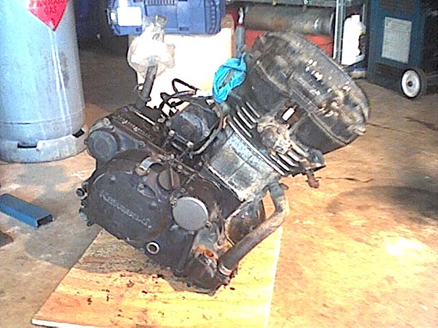
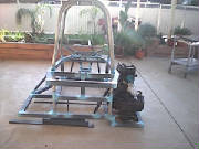
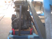
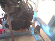
The doner bike that i am going to use for my buggy is a 1988 model road/trail Kawasaki KLR650. It is water cooled and has
electric start which are the two things which i wanted. I brought the buggy from a guy in the trading post for $1300
and it seems to be in perfect running condition. I might pull it apart later on though once everything is together and running
just to check the condition of the internals. It is also fitted with a Staintune performance muffler which is a plus. I
am currently pulling all the pieces off the bike, fairings/seat,e.t.c which are not required for the bike to run and i am
selling them on ebay to get some extra money for the buggy project. The parts which i will use from the bike are the engine
and all the gear for it to run, the instrument cluster and also the clutch lever (will be attached to gear shift lever)..
I will extend and modify the original bike wiring harness using the wiring diagram from the haynes manual i purchased. I plan
to purchase a small car radiator or maybe even a large bike radiator fiited with a fan, whatever i find first that is suitable
for the job. A small car battery will also be purchased to replace the small bike battery as i plan on running two large spotlights
as well as a tail/brake light.
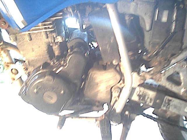
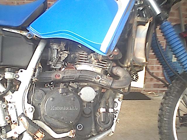
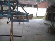
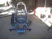
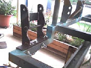
Below is pictures of the bike with motor still installed and with the fairings removed.
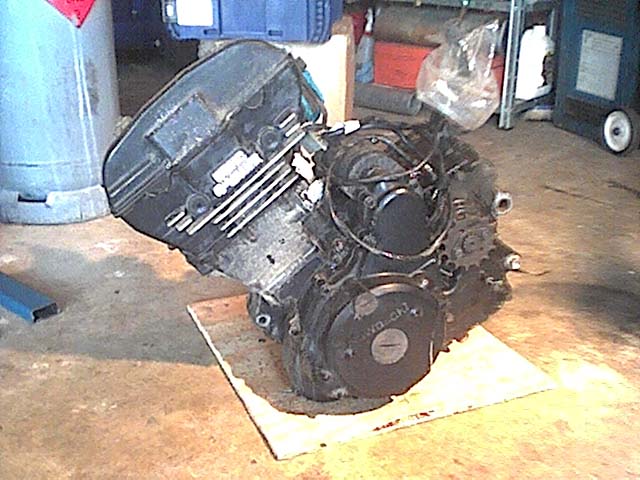
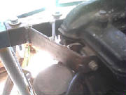
I finally got the motor removed from the KLR, it was a bastard to get out. All of the mount bolts came out easily except
for one which is located at the rear of the engine and acts as the swingarm pivot bolt as well as the engine mount bolt.
The swingarm bearings must not have been serviced regulaly as they had seized to the pivot bolt making it impossible to remove
the bolt. I tried hitting it out with a sledgehammer to no avail. I then ground the head off the bolt and tried hitting the
bolt out the opposite way also to no avail. I then attempted to drill out the bolt, its a 15mm high tensile bolt so it turned
out to be a big job which blunted a lot of drill bits and also killed my old 2 speed drill which gave me an excuse to go buy
a new flash AEG power drill. Drilling the bolt did not work. After all that i came up with the idea of removing the bikes
rear wheel and removing the rear shock which would allow me to move the swingarm out of the way so i could attack the bolt
from behind. I ended up using a cutting disk on the angle grinder and i cut through the bolt in between the engine mount and
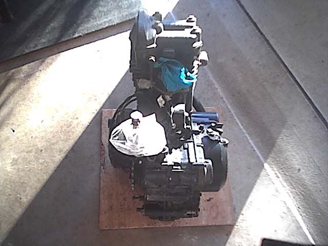
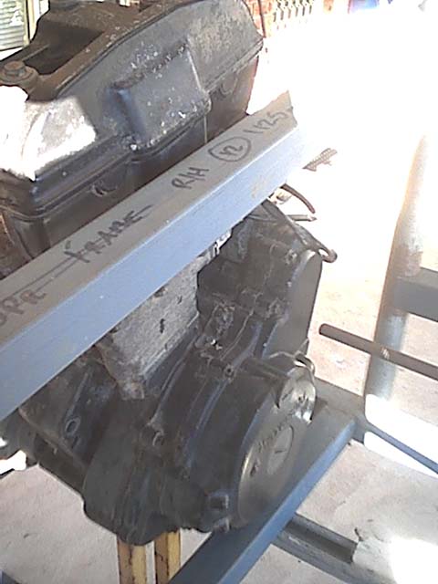
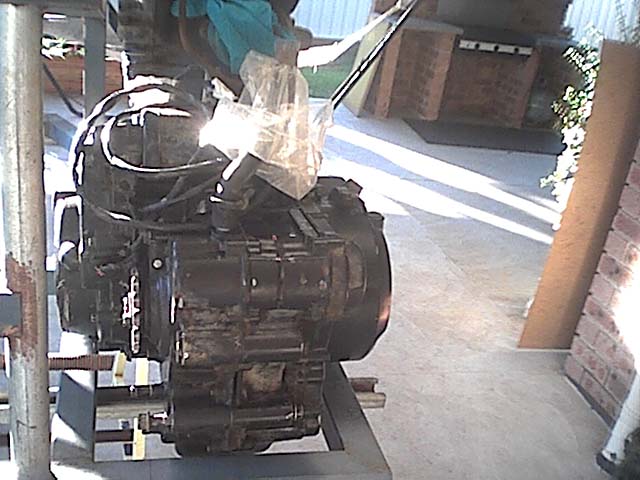
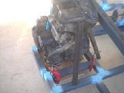
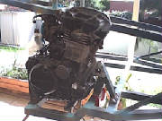
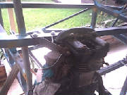
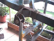
the swingarm very carefully which worked, should have thought of that in the fist place.... engine weighs prob 40-50kg (i
can just lift it myself) heres some engine pics, it will get a new paintjob once its fitted to the winder.
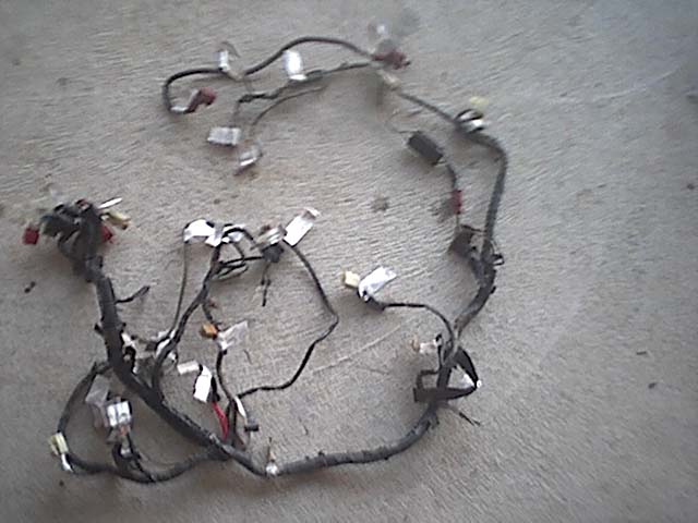
This is the wiring harness from the bike, i will use it on the winder, it will be lengthened where required to reach different
components. Looks like a mess but i have it all sussed out. The key here is to label all the connectors and switches when
you remove the harness from the bike, that way it can all just fit back together with minimal fuss.
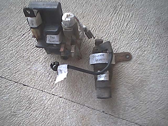
These are the relays from the bike, including starter relay, fan relay, CDI unit, e.t.c. They were mounted to there own
small frame on the bike so i plan to use the same frame and mount them directly to the winder. I plan to mount them between
the rear suspension pivot plate and the rollbar on a peice of aluminium plate so it is behind the seat. Should fit sweet
as there is about a 150mm x 150mm space there.
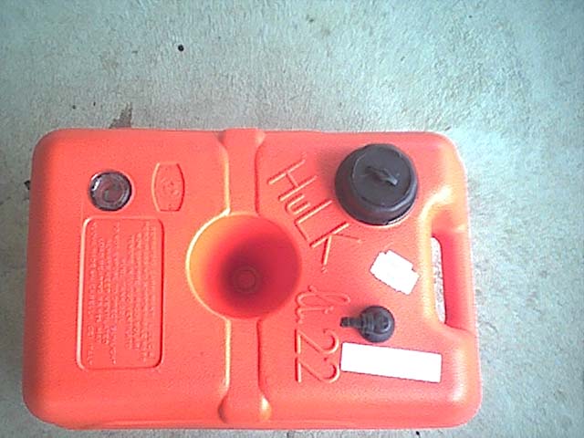
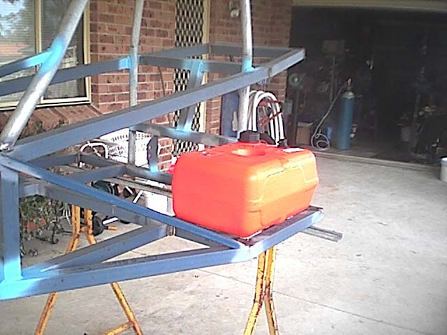
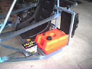
Below is the fuel tank that i will be using for the buggy. Its a 22 litre plastic marine tank made for outboard motors,
e.t.c. Its the perfect size to fit on the r/h wing. Its called a hulk and costed $60. It came with the filler cap and the
fuel outlet barb with a built in mesh filter.
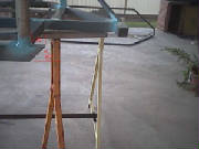
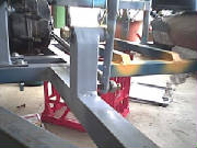
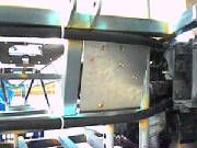
The Frame Modification
In order to get the sprocket of the motor in line with the pivot point the frame needs to be notched down approx 60mm
as many others have had to do to their sidewinders. I am also going to relocate the lower inner rail inboard by approx 60mm
to allow the engine to be as close to the centre of the buggy as possible. Below is how i modified my frame to fit in the
motor. Feel free to do the same but if it doesnt turn out how you wanted then dont blame me. Haha. Mine came out very well.
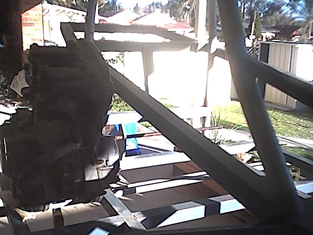
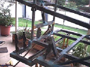
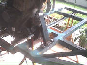
Below are some trial fit pics of the engine in the buggy so you can see where i am going to have to move the
frame to lower the engine down so it works properly.
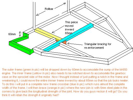
Below is a rough picture of how i plan to modify the frame to fit the engine. I drew it up in paint and as you can see
im no artist, but you get the idea of whats going to be moved where.
I am now starting to modify the frame, i will first relocate the inner rails to their new positons, i will notch the
outer frame down later once the inner rail mod is completed.
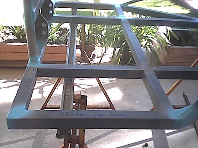
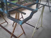
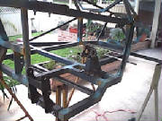
Below is a picture of how it looks before i got the grinder to it and cut it up.
Below is what it looks like after i have cut out the inner rails which i will replace later on.
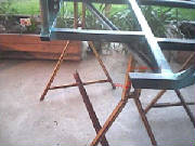
The rails which were cut out....
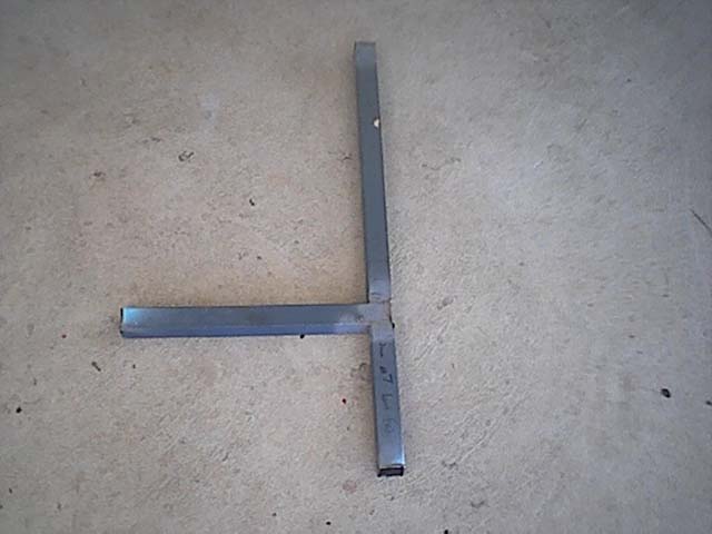
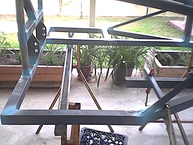
Below is a picture of the new cross rail tacked in place. It is now a complete peice running from the l/h side inner
rail to the r/h side outer rail. To get to this step from the first frame cut took me about 1.5hrs.
Below is a pic of the new inner rail fitted. In the end i moved it toward the centre of the buggy by 58mm from its original
position.
Ok, now its time to do the outer rail mod. By sitting the engine in the frame and taking measurements i figured that
i would need to drop the frame by 68mm.
The pics below shows the where the frame was cut to the angles required. I cuts were made 110mm rearward from the side
rail and 35mm from the rollbar. Angles cut were 45 degrees on the rear and 67.5 degrees on the side as well as 67.5 degrees
on the peice which will be added to the side to drop it down. This will mean that the side will slope down at a 45 degree
angle.
Ok, now that the angles are all cut its time to set the frame up to get the 68mm drop height. I did this by finding a
flat peice of ground (my garage floor) and then i propped the frame up so it sits 68mm off the floor. To get the height i
used a peice of 40x40 rhs, a peice of 20x20 rhs and a scrap bit of 8mm plate stacked on top of one another. Then i just sat
them under the frame at various places like in the pic below.
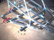
Now to make sure that the dropped down peice is going to be inline with the frame once it is re-attached i just used
some steel clamped to the frame as a kind of jig to keep it all in line as shown below.
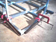
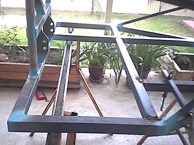
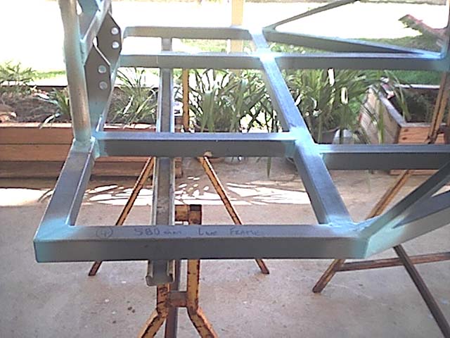
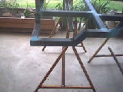
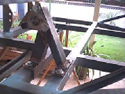
And thats about it! Once you have the drop down peices cut just put them in position check for squareness, e.t.c and
tack it. Below are pictures of the frame mod completed, overall it took 3 afternoons to do which included moving the inner
rails and dropping the outer frame as shown.
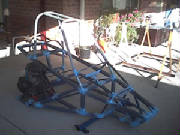
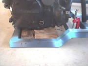
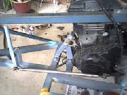
I didnt have the welder today because i lent it to a friend who needed it. So i decided that i would put the motor
in the frame and see how it all fitted up and to see how it looked. Below are some pictures of the motor installed in the
frame in pretty much the exact position it will sit when installed. It just needs to be squared up a bit more with the frame
and then i can start making the mounts.
The picture below shows the gap between the cylinder head and the upper frame side rail. The gap is about 10mm.
In the below picture you can see the packing i used under the engine to get it sitting in the correct position. The packing
is just made up from scraps of wood i had laying around.
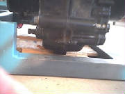
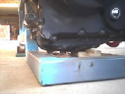
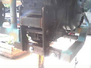
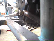
The two pictures below show the main reason why the frame needed to be dropped down to accomodate the engine. The back
section of the motor sump would have prevented the motor coming down low enough to line up the pivot point and motor sprocket
had the frame not been notched down. You can see a better view of this in the second picture.
This picture shows that the rear suspension pivot point lines up with the centre of the motor drive sprocket. I just
put a peice of bar through the suspension pivot plate holes and then moved the engine around until the points lined up. Make
sure that the word "Kawasaki" on the side of your engine case is pretty much horizontal with the frame when mounting the motor.
Making Engine Mounts And Mounting The Motor
Making the engine mounts was actually a lot easier than i had first anticipated.
What i did was i sat the buggy on the ground and ensured that the frame was sitting perfectly level. I then put the engine
in the exact position for where it needed to be located. This included lining up the centre of the engines drive sprocket
with the rear suspension pivot point, ensuring that the motor was level (in my case that the word "Kawasaki" on the engine
case was horizontal to the chassis to ensure correct oil flow in motor) and also that the motor was sitting square in the
chassis both front to back and sideways.
I chocked it up into the position required with just peices of scrap wood and i then built the mounts around the motor.
I found the easiest way to make the mounts was to cut the angle first and clamp in to the frame in position, and then cut
the parts to fit between it and the motor mount hole.
I used the three mount points on the engine which are on the front, on the rear and one on the rear of the cylinder head.
All three mounts have been made so they are completely removable from the buggy frame. This will make installing and
removing the engine from the buggy much easier.
Pictures of the mounts and of the motor in position are below.
Below is pictures of the front engine mount. Its made from a peice of 40x40x5 angle, 50x25x3 RHS and 40x40x2 RHS.
I also used the original triangle mount from the bike as part of the mount. I drilled out the mount hole on the motor to take
a 1/2 inch high tensile bolt because i could not get a bolt to fit the original hole diameter. The entire mount is completely
removable and is held to the frame with 3/8 inch bolts.

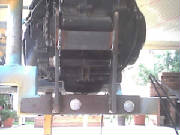
Below is pictures of the rear engine mount. The rear engine mount was made from 40x40x5 angle and 50x8 flatbar. Their
are actually two rear mount holes on the KLR engine, one at the bottom of the rear and one about halfway up the rear. I
have incorporated the mount to use both of them even though the pictures show a bolt through only the lower mount position.
The upright peices of flatbar which the bolts go through had to be shaped to fit around the curved sections on the rear of
the motor gearbox as can be seen in the pictures. This was just done with a grinder and file. I made a template of the uprights
using cardboard first to get the shape correct.
I also made the peice of angle which fits around the frame longer on the left hand side at the rear as can be seen in
the rear view picture. This is so i can attach the chain tensioner to it at a later date.
The bolt in the lower mount is 7/16 inch diameter and the entire mount is once again bolted to the frame with 3/8 inch
bolts.
The cylinder head engine mount was made using 40x40x5 angle and 40x6 flatbar. This mount had to be made to fit in
the small amount of room between the cylinder head and the carby, thats why i used the flatbar to make it.
I drilled the cylinder head hole on the engine out larger to 3/8 inch to take a high tensile bolt.
Once again the mount was bolted to the frame with 3/8 inch bolts.
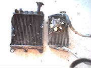
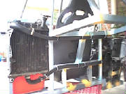
Picked up a larger radiator today for the buggy. Its off a 1975-80 model GL1000 Honda Goldwing. Its about twice the size
of the KLR650's original radiator and about 2cm's thicker as you can see in the picture below. The new radiator is on
the left. I traded some of the parts which were left over from dismantling the KLR650 for the radiator which means i got
it for free from the wrecker which was good as i got to get rid of some off the useless stuff i had laying around and
i got a perfect radiator in return. Its the perfect width to fit above the fuel tank on the left wing of the buggy. I will
just transfer the KLR's fan and thermostat over to the new radiator. The increased size of the radiator should now have no
problems keeping the engine cool even on hot days.
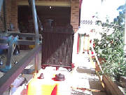
Just a sample picture of whereabouts the radiator will sit. I emailed Tony at the Edge and he said this is the optimum
position as it gets plenty of airflow in this position and also helps to counter act the weight of the engine on the right
side of the buggy to give better balance. Just have to fabricate mounts for it now...
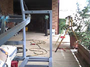
Ok i have now made the frame up for the radiator to mount to. Its just made from 30x30x2 RHS. Was a pretty simple design.
I designed it so the radiator would sit above the fuel tank and would get plenty of airflow to cool the radiator whilst the
buggy is on the move. Pictures of the frame below.
Below is a picture of how i have routed the radiator hoses from the radiator to the engine. The hose i used is 19mm
inside diamter heater hose, its the biggest size i could find that came in long enough lengths. It just fits over the fittings
on the engine with a very tight squeeze. However because i am using a larger radiator from a bigger bike (GL1000), the
19mm hose didnt fit over the radiator fittings so i had to use bigger diameter hose to attach to the fittings on the radiator.
I then just put a peice of tube inside the 19mm radiator hose, then inserted the 19mm hose inside of the larger hose and then
put a clamp around them to make it watertight. The peice of tube being inside the 19mm hose to stop the clamp squashing the
hoses when tightened. Hose costed about $30 all up for 4 metres of 19mm hose and some larger hose to adapt the radiator. You
can see in the picture below how i did it. The hose joins are located just after the hose leaves the radiator.
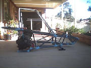
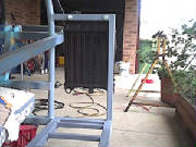
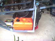
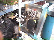
Pictures below of the completed radiator setup. The radiator sits very well in its position and should have no worries
keeping the motor cool. Also in the picture you can see where i have mounted the battery.
Gear change setup
Well today i set up the gear change system. Its my own design, as using the design in the plans was not going to work
efficiently because i couldnt downshift properly as i was not getting the correct leverage on the engine shift linkage to
move it downward. My design overcame that problem but resulted in me having to move the shift lever down further in the drivers
compartment to get nice positive shifts everytime i moved the lever. I like the design, i think it looks pretty sweet, and
its quite comfortable to use as well.
I basically took the original gear shift foot lever and cut the foot grip section off with a angle grinder to give a
flat section which i could bolt through to attach a tie rod end. A tie rod then runs from the engine shift lever to the hand
operated shift lever which is located on the right side of the drivers compartment. I used the Edges shift lever which
i brought from them and then made up my own custom mount for the lever to pivot on, it came up looking nice. Now with
this layout i have a nice straight connection between the two shift levers via the tie rod which will result in nice
positive gear changes. Pictures below.
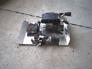
Made a holder plate made up of aluminium to keep all the relays, cdi, regulator/rectifier, e.t.c in one place in
a tidy looking fashion. It just made from a peice of aluminium about 3mm thick which i bent up so it can fit between the frame
behind the seat and mount to the frame with self tappers. It keeps the electronics up out of the way of dirt and water
and also hides them behind the seat so they are not seen. Pictures below.
|